Warm Tube Clock sat v2
Moderators: pedja089, stojke369, [eDo], trax
Re: Warm Tube Clock sat v2
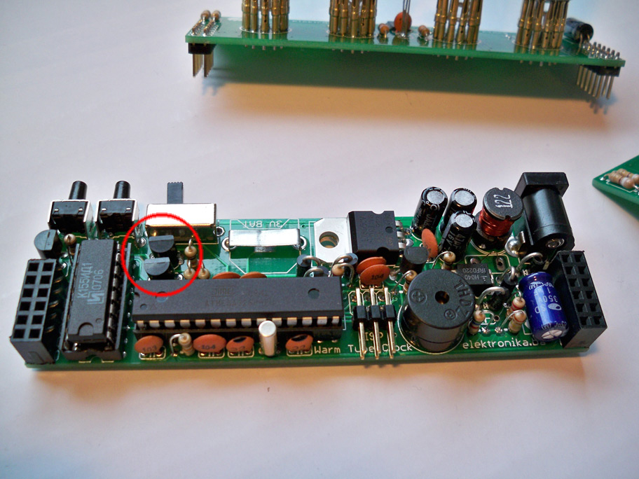
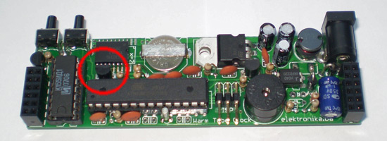
Ok, I have been looking at the schematics and I see the two NPN KSP42 transistors, but I cannot figure out where the second one goes on the V2 board.
ON the V1 board I can see the two of them...
but int V2 I can only see one.
ON the V1 board I can see the two of them...
but int V2 I can only see one.
Re: Warm Tube Clock sat v2
The component left to it is also transistor. On v2 there is no DS1820 temperature sensor.
To make sure yourself, please open the project files in Cadsoft Eagle. You need to open .BRD file.
I really need to publish the pdf with component placing instructions :-/
Let me know what happens. I am on my phone now so I can't open these files myself.
To make sure yourself, please open the project files in Cadsoft Eagle. You need to open .BRD file.
I really need to publish the pdf with component placing instructions :-/
Let me know what happens. I am on my phone now so I can't open these files myself.
Re: Warm Tube Clock sat v2
Here, you can use this PDF as a reference for assembling the V2 main board.
www.elektronika.ba/misc/warmtube_v2_main_assy.pdf
Re: Warm Tube Clock sat v2
Trax, thanks for this, it is very helpful. My project keeps getting side tracked due to work, slowly but surely it will get done.trax wrote:Here, you can use this PDF as a reference for assembling the V2 main board.
http://www.elektronika.ba/misc/warmtube ... n_assy.pdf
Re: Warm Tube Clock sat v2
I am slowly moving along, actually I am making 3 clocks at the same time, (2 wedding presents and one for my self) 2 of them are IN16 and one is IN14 and I have a question about the IN14. The assembly instructions are for the IN16 nixies but on the IN14, for the R3, R4 and C3 there are 3 smd pads under TLC59401 are these for the SMD R3, R4 and C3? and if so what order?
I did go over the schematics and studied the circuit board but I can't figure it out. There is another SMD pad beside the C1, 47uf capacitor I assume this is for the C2 SMD capacitor.
Re: Warm Tube Clock sat v2
I will get back to you on that today, when I get home from work. I can't open the design files here...
Re: Warm Tube Clock sat v2
Here, take a look at this image and see if it helps.
- Attachments
-
- in14_smd.jpg
- IN-14 nixie shield component placing
- (691.43 KiB) Not downloaded yet
Re: Warm Tube Clock sat v2
FYI
Please do not solder Nixie tubes to the other side of the PCB. It never occurred to me that someone might do that until I read what you said: "there are 3 smd pads under TLC59401". There is actually TLC59401 under the SMD parts
TLC59401 is on the PCB bottom side, but those three SMD components are on the top. Please take a look at the photos at the project page of both shields to not make that mistake:
http://www.elektronika.ba/786/warm-tube ... nixie-sat/
http://www.elektronika.ba/800/warm-tube ... nixie-sat/
Re: Warm Tube Clock sat v2
Thats super Trax, and now I am back on track.
Thanks for the heads up with which side to solder the nixies, I am pretty sure I would have gone for the option of putting the TLC59401 on the bottom side, but sometimes I am capable of making those sort of mistakes.
Re: Warm Tube Clock sat v2
I finally started assembling the clock
I have some questions about the v14 shield. Is it correct that I miss the 103 capacitor and the resistors R3 and R4?
I also not sure about the location of smd capacitor c2.
What is the purpose of the 6 square solder pads between the opto couplers?
There are also two square solder pads below the most right opto.
Re: Warm Tube Clock sat v2
Hi,
Nice to hear that you started the assembly process. You must solder all components, do not miss anything
I do not know what solder pads you are referring to, between the opto couplers? Maybe you can attach a photo here?
Regards!
Nice to hear that you started the assembly process. You must solder all components, do not miss anything
I do not know what solder pads you are referring to, between the opto couplers? Maybe you can attach a photo here?
Regards!
Re: Warm Tube Clock sat v2
Thanks for the reply!
I have attached an image. And circled the solder pads in red.
- Attachments
-
- nixie-pcb.jpg (28.4 KiB) Viewed 13696 times
Re: Warm Tube Clock sat v2
Yes, those are the pads for SMD 0805 resistors and capacitors. Please refer to schematics to see which component values you need. I am at work now and I don't have Cadsoft Eagle here to check that for you.
Don't forget that you also have SMD pads under the Nixies, those are for SMD RGB LEDs
You might also check this out: http://www.elektronika.ba/misc/shield_in-16.pdf
Don't forget that you also have SMD pads under the Nixies, those are for SMD RGB LEDs
You might also check this out: http://www.elektronika.ba/misc/shield_in-16.pdf
Re: Warm Tube Clock sat v2
Thank you, I will check the eagle file.
The smd leds are already in place
Re: Warm Tube Clock sat v2
In case you didn't check with Eagle, here it is.
- Attachments
-
- smd_placement.png
- (23.72 KiB) Not downloaded yet
Re: Warm Tube Clock sat v2
Thank you for the image!!!
I ordered the smd parts (and waiting for the opto couplers and usb programmer from china).
Re: Warm Tube Clock sat v2
Hello, I'm back, with more annoying questions to try and finish my 3 clocks.
I got all my soldering finished just before new year, did test 1 and could not get a reading. . I decide to see if I could figure out the problem my self and spent some time going over the schematics, checking the solders etc but I couldn't get the 3v reading. So I put the project down and allowed my self to get busy with everything else, work, renovating the house, raising two small kids...
So now I have forced my self back to finish this project. Too much time and energy put into it to give up.
So.. I went through all the steps again today, checked everything and have some conclusions/questions. IN the first test, it suggests that if there is no reading that diode D4 is orientated incorrectly, but there is no D4 diode in the V.2 clock.
Step 4 - none of the 3, 1N5817 diodes are on the board.
Step 10, the zener diode is not in.
step 12 there is no 75 ohm resistor.
Step 20 I have not soldered in the buzzer as it has no polarity marking on it and touching it off a 9v battery doesn't make any sound. its this one https://www.adafruit.com/product/160.
Are any of the above causing a problem with not getting the 3v charge.
Re: Warm Tube Clock sat v2
Hello,
Nice to hear that you decided to finish the clock. Do not worry about these problems, you can solve them. The clock must work properly at the end
I understand that you are following assembly manual for v1 when you are assembling v2. That can be rather confusing but manual for v1 can serve as a guideline, at least.
Looking at the schematics from the above link, you need to correctly solder the diode D1. If you don't, the power can't get through and nothing will work. I am at work now and I do not have Eagle installed here so I can't open the .brd file to tell you what direction you need to install this diode at. Can you open the file yourself and see how to properly solder/orient the diode (anode-cathode)? Also, you need to solder the fuse.
After you do that, and before placing AVR microcontroller in place, you can power up the board and measure the voltage at AVR's pins: GND and VCC. You should measure 5V there. If not, then there is no power.
You do not need the Zener diode in the clock, you can ignore it completely. It is just for safety.
The 75ohm resistor is in the schematics in series with the speaker. And in v2 the value is actually 47ohm (R10), but you can use 75 instead. This limits the current for the speaker you mentioned from Adafruit website. Do not connect the speaker to 9V battery, because it is actually not a buzzer, it is a speaker. But because you already did that, you now need a multimeter to measure the resistance between the speaker pins. If there is small resistance - it is OK, but if the resistance is infinite (0L) then you need a new one. The polarity for this speaker is not important, do not worry about it. It should work both ways if the polarity is not marked on the speaker you have.
I do not know where you are expecting to measure the 3V? The clock works at 5V! The only place you will see 3V is at the backup battery for the RTC chip.
You could also make some photos of your work, maybe we can see the problem that way.
Best regards!
Re: Warm Tube Clock sat v2
Hi Trax,
I really appreciate you taking the time to help me get this finished.
The 3v I was searching for is from test 1 after completing the mainboard. It said before attaching the power supply, put in the battery and test across the GND and the VCC and see if it reads 3v. Which it didn't, so I decided not to connect the power supply in case there was a problem.
At this point I have to say I have the worlds shittiest multimeter. I don't remember when I got it but when I was looking on ebay for a better one (now ordered) I saw it was on sale for €3.
So I powered up the board and I am getting 4.25v - 4.32v across the GND and the VCC. It should be reading 4.8v.
I continued with test 2, and was getting consistent readings of 4.25v - 4.31v on all the points except for the IC4, of course on warmtube clock v1 this is a temperature sensor and now on V2 its a NPN KSP42 transistor.
I did test 3 and got 12v across the voltage stabilizer and the 1uf capacitor.
So far so good, I think.
I guess I have blown the speakers, so another 3 ordered today
Re: Warm Tube Clock sat v2
Hi,
So far it looks OK. Maybe that voltage is a bit lower than expected - 5V, but again maybe it is the crappy multimeter
Regards!
So far it looks OK. Maybe that voltage is a bit lower than expected - 5V, but again maybe it is the crappy multimeter
Regards!