comment [16]
- From trax on 02-08-2018 at 21:34:01
I have a couple of these assembled... send me an email: trax at elektronika.ba and we can talk.
IP: n/a
This project is a revisit of my single channel loop detector from 3 years ago and it comes with some cool new features.
There are two PCB versions available, one is a standalone version (PCB v1.2) with DIPs and relays on board and another one is a digital version (PCB v1.3) without DIPs and relays where it requires PC or another microcontroller system to be connected in order to configure the operating parameters. Here we will be focusing on the standalone version.
UPDATE 2019-12-11: New, unpublished version available on Tindie.
UPDATE 2018-03-19: Pre-programmed PICs are available for purchase here.
UPDATE 2017-09-25: PCBs are available for DIY assembly:
- PCB v1.2 (standalone version) is available for purchase here, BOM and assembly instructions are also here.
- PCB v1.3 (digital version) is available for purchase here, BOM and assembly instructions are also here.
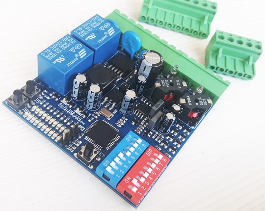
DLD PCB v1.2 (standalone version)
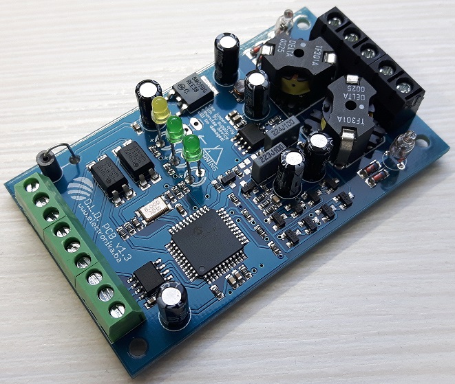
DLD PCB v1.3 (digital version)
Specifications
User Manuals and PC Configurator software source code
All user manuals are available for download in the ZIP archive (the red download button under the article). However, here is also a direct link for the user manual for PCB v1.2, FW v1 on this link (PDF), and for PCB v1.3, FW v1 here (PDF).
PC Configurator user manual is here (PDF) and source code is on GitHub here.
Modes of operation
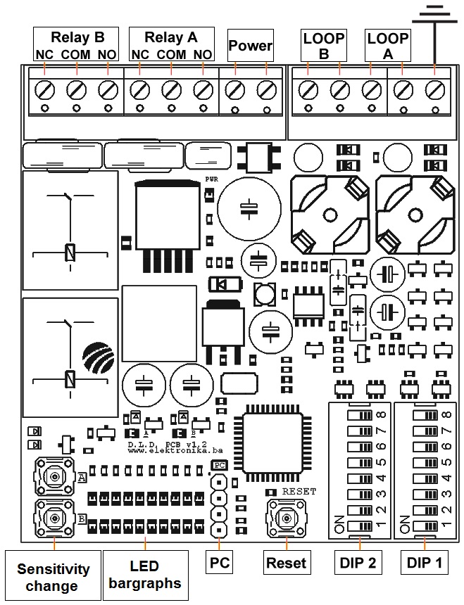
Pinout of electronics for PCB v1.2
Hardware
Hardware differs from previous version in many ways but the essence is the same - it counts pulses coming into RA4/T0CKI pin and performs the same filtering and calculations in order to detect the change in frequency of oscillation. This time, it does that twice for both channels independently.
There were two possibilities on how to implement dual channel loop detector and one of them (and unfortunately widely used) is by using two independent oscillators on board while having them enabled/disabled one at a time in order to read loop A and loop B frequency. The other method is by multiplexing two (or more) loops on one single oscillator on board. I have chosen the second method because it just seams better to have one oscillator and two loops instead of two oscillators each connected to one loop.
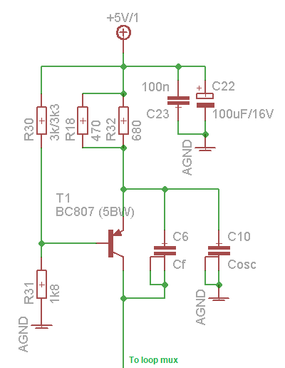
Oscillator without connected loops
It was quite tricky to enable/disable a loop in an oscillator so in the end I had to offset the multiplexer circuit to half of supply voltage (Vcc/2) and opted to use simple PNP transistors connected in parallel but in opposite direction so that one conducts positive half-wave and the other one negative half-wave of the oscillator signal. I first tried using CD4066 but with no luck.
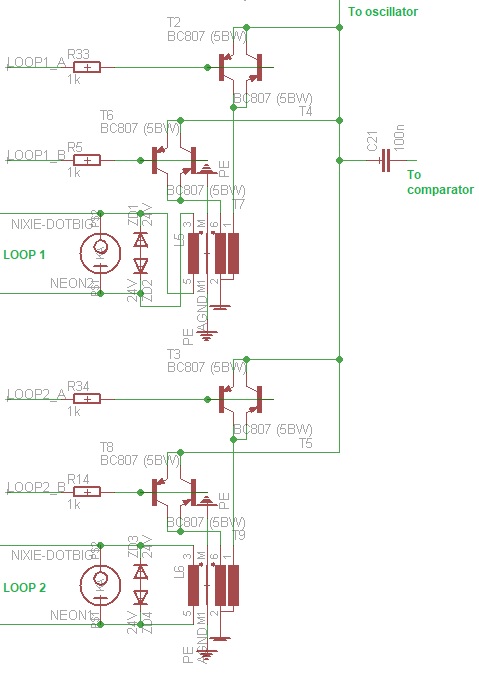
Multiplexer
Offsetting voltage to Vcc/2 is done with TL431 2.5V precision reference voltage regulator, as it was extremely important to have a stable reference. Zener diode also works here but it does not have the required temperature stability so it was out of the question. Since now I had a way of connecting/disconnecting loops to the oscillator I decided to put an additional multiplexer for each channel to provide a way of choosing an alternative oscillator frequency. This was done by adding another winding/coil to primary of the transformer (the side that is connected to the oscillator).
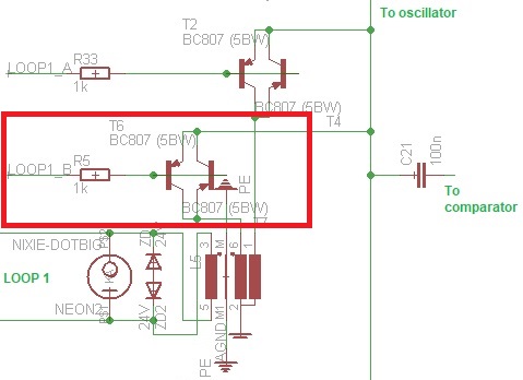
Choosing alternative frequency
This way instead of having an additional capacitor + switching transistor in the oscillator we have an additional winding/coil in the isolation transformer + an additional multiplexing circuit. I actually copied this idea from some other high quality loop detector before and decided to do the same here. It would be a small change in firmware and hardware in case it is required to go back to the more conventional way of changing the oscillation frequency with an additional capacitor(s).
Since our oscillator signal is now offsetted to Vcc/2 I had to use a comparator circuit to decide when sine wave is positive (>Vcc/2) and when it is negative (<Vcc/2) in reference to our "floating ground" which is at Vcc/2.
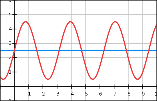
Sinewave signal
First I decided to reduce the part count by using PIC's internal comparator circuit to perform the job of deciding when signal crosses the "zero" point (Vcc/2), and this is where I originally made a bad decision. It actually worked fine until I increased the sensitivity setting of the device, then it started to behave strange. I simply could not get a stable reading from the frequency counter, sometimes it was off by ~1 Hz and sometimes even more. Since ~1 Hz was too much for me to ignore I had to track down the problem. After hitting my head on the desk for a long long time I figured out that it was the PIC's internal comparator and also unstable Vcc/2 "floating ground" rail. It would seem that the comparator was not making its decision correctly every single time. This was due to fluctuations of the comparators power supply which is unfortunately connected to the same point as PIC's Vcc. Even turning on a simple LED connected to microcontroller's pin the comparator would make a decision few microseconds off. This was driving me crazy so I re-designed the device to use external comparator LM211 where I could filter its supply rail and somehow isolate Vcc of microcontroller and Vcc of comparator. This was done by using two capacitors and a 10uH inductor. Now this little filter makes all that difference and is a very important part of the device. I also added capacitors to make Vcc/2 "floating ground" more stable.
For same filtering reasons I added LM78M05 stabilizer to increase the Vcc rail stability because relays make a proper power draw when they turn on. These are now powered directly from a step-down converter that steps down from any input voltage to some +10V and then everything else digital is powered from the LM78M05.
Note: I could have probably done it without this many capacitors in the device, but I didn't want to risk it. Also, it is quite possible that I haven't properly stabilized the Vcc/2 rail with capacitors during testing with internal comparator, so it is possible that internal comparator could actually do the job. But since the firmware must be a bit different for internal comparator version, I will not be trying that option any time soon (or ever, for this project).
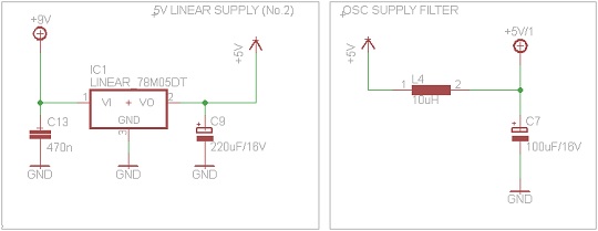
Filtering Vcc for comparator and oscillator
Finally, simply connecting the output of comparator to RA4/T0CKI pin of microcontroller was not possible since by adding pull-up resistor to output we would introduce all those voltage stability issues that we avoided so I had to put another NPN transistor just to once again separate Vcc of comparator from Vcc of PIC. Ideally an opto-coupler could be used here, but NPN transistor is smaller and cheaper and works just as well.
Aside from multiplexing two loops, there are also two buttons, two DIPs and two bar-graphs to control. These are also multiplexed at the same rate as the two loops with two NPN transistors on board. Multiplexing DIPs and buttons can't be done without diodes at each input so I had to use them. Interesting thing about the diodes connected to DIPs is that I could not find a diode array to use and I simply did not want to put 16 diodes on my PCB (for obvious reasons - 16 diodes!), so I opted to use SRV05-4 SOT23-6 Low Capacitance TVS and Diode Array in a way they were probably not designed to be used in. I use these devices just as a diode array where they do not perform any TVS protection and this saved a lot of PCB space. Alternative was to connect 16 diodes on the bottom side of PCB but that would be ridiculous and also harder to manufacture. This way all components are only on the top PCB side.
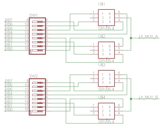
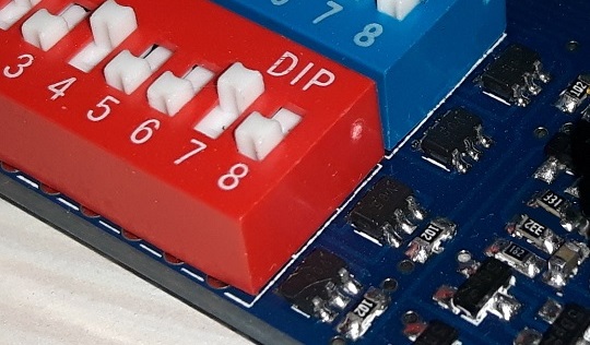
DIPs and their diode arrays
Transformers used in this device are repurposed ADSL DELTA (RM-5) Band Stop transformers, rewound manually to roughly 1:1 with a "tap" in secondary. This tap is for the alternative frequency selection that I was talking about earlier. Inductance of transformer is therefore anywhere around 3.6mH for primary, 3.6mH for secondary and 3.55mH for secondary at "tapped" output. The inductance is really not cricital. You can see how transformer is made in the video bellow.
Making isolation transformers
Important differences between standalone (PCB v1.2) and digital version (PCB v1.3) are:
Speed Trap
The most interesting mode of operation (for me, at least) is Speed Trap. The device is able to measure speed of passing vehicles in both directions, and when configured properly it can do so with little error. It can (theoretically at least) perform as requested by this document http://www.ukroads.org/webfiles/tr2512a.pdf regarding the speed measurement errors.
It could, for example, be used in combination with another microcontroller device to display vehicle speeds on big LED displays or even standalone to trigger a camera to take a shot when vehicle exceeds configured speed limit.
The maximum time measurement error is supposed to be 2*sampling speed. The measurement method works this way: Two loops are multiplexed (multiplexing period is of duration of one sampling speed/period). When a vehicle triggers any of two loops, the multiplexing process stops and device waits for vehicle to exit the first loop. Upon exiting the first loop device starts time measurement and here we need to take into consideration that vehicle most probably did not exit exactly at the end of current sampling period, therefore we accumulate error as a duration of one sampling period. Now device disables that first loop and enables second loop to expect the vehicle to enter and leave the second loop. Once it leaves the second loop the process is complete and we have our measurement. Also we need to take into consideration that vehicle probably did not exit second loop at the end of sampling period so we need to accumulate one more sampling period to our error.
Influence of these accumulated errors to final measured speed is displayed in PC Configurator Software for each chosen sampling speed and loop distances. This way user can configure the device to achieve the requirements for maximum allowed measurement error.
Firmware
Firmware has been almost completely rewritten in order to provide reading and processing of two (or more) loops. Here I am saying "or more loops" because the device can be extended to more than two loops quite easily. Because of many new features I had to switch to different microcontroller, this time to PIC16F1939 because this one is the best one my current compiler (HI-TECH C) can compile the code for. I am also thinking about porting the code to some PIC18F microcontroller and implementing a bootloader to provide firmware updates in case new features are added or bugs are found later on.
If you have not already read how the firmware of previous version work, it would be best to do it here. This dual channel version works basically the same with some logical and obvious changes that had to be incorporated to support two channels and multiplexing of user-interface (bar-graph, buttons and DIPs). So old features will not be described here again, we can just focus on new stuff.
Detect Stop feature is a feature where it is possible to energize a relay or call a detection only when (and if) vehicle has completely stopped over the loop. This means that passing vehicles over the loop would not be detected, only those that come to a complete stop would.
Positive Frequency Drift Compensation feature (or Drift Compensation During Detection) is a feature where device will re-adjust itself to new baseline even during vehicle detection. This can be a tricky thing that could potentially cause a stuck-detection if configured poorly. This comes in handy for vehicles that park over the loop for longer periods of time. This method will start tracking the baseline (drift) when vehicle has been detected as completely stopped over the loop. Once the "no-movement" threshold is crossed it will pause the compensation and resume if the vehicle remains detected and stops moving again. Causing the stuck detection can be done when a metalic object (usually not a vehicle because it is bulky and is not able to make that small change) is first detected, stopped, and then very slowly moved away from the detection zone. This would make the detector believe that metalic object has actually not moved away, but instead that it was just a frequency drift. Luckily vehicles can not perform this small change even when moving very slowly so this should not be a problem in real-life usage.
Smart PPC recalibration feature is actually a re-implementation of how permanent presence canceller operates once vehicle has left the loop. It will detect when there is absolutely no movement once the vehicle has left the loop in order to recalibrate itself.
Fail Safe feature is an option to energize relays upon device startup until first detection occurs. This should prevent barriers from closing down on vehicles in case there was a power outage while the barrier was "up".
Reset To Factory Defaults feature is a feature where after poking around the PC software and re-configuring the device to some faulty values it is possible to restart it to default factory operating conditions. This can be done by holding both sensitivity-change buttons and restarting the device.
DIP switches
DIP switches have different meaning for each operating mode, and these are explained in the user manual which is available for download bellow (the red download button under the article).
PC Configurator Software
In this software it is possible to customize the device by configuring every operating parameter it contains. It is also possible to view detection and speeding events and view magnetic signatures of passing vehicles and store them as files for further analysis.
PC Configurator Software is explained in detail in dedicated "pc configurator user manual" file which can also be downloaded by pressing the red download button under the article.
In that same file there is a detailed description of UART protocol that device uses which will come in handy when device is to be connected to another microcontroller system especially for digital version (PCB v1.3).
Important notice
Major difference in sharing this version of project and the previos one is that firmware is currently not available for download, but I can send you preprogrammed microcontroller for the cost of only microcontroller + shipping (or you can even send me your microcontroller(s) and I will send them back programmed). Sorry about this, but I had a few situations with sharing firmware of the previous version - some people did not respect the agreement that I put with the firmware and I strongly believe that they are manufacturing it and selling copies of the device which was not permitted. Other files can be downloaded by clicking the red download button under the article, and hopefully the firmware will be soon available for download.
Assembly
Part placement diagram, bill of materials and stencil Gerber files are in ZIP archive available for download by clicking on the red download button under the article.
Assembly of PCB v1.3 - digital version
Author (sent by): Trax
Download counter: 1,209
Rating: 


 (3.20, votes 1633)
Date: 01-09-2017
Lokalna verzija ove stranice: Dvokanalna induktivna petlja za detekciju vozila
Tags: detector, ild, inductive, loop, pic, pic16, pic16f1939, vehicle. +add your tag
Hi,
Is there any way I could get a fully assembled & tested board v1.3? I need 2 of it.
many thanks
IP: 138.201.205.167
I have a couple of these assembled... send me an email: trax at elektronika.ba and we can talk.
IP: n/a
Can I buy one of these pre-assembled?
IP: 138.201.205.167
...so that I can place two sizes of capacitors :)
IP: n/a
Hello Faythx. Cross-talk is when oscillations of one loop influences the detection of other
loop (interference) and causes a detection on that other loop even when there is no vehicle
present. That is avoided by multiplexing or having only one oscillator active at a time. For 3
channels, it does not matter whether you use three oscillators or multiplex three loops on a
single oscillator. If you need all three oscillators running at the same time (ideal for speed
measurement) then they would need to have very different frequencies so that there is no
cross-talk. It is always a good idea to filter VCCs for each oscillator. I did not try 3
oscillators design. It does not matter what transformer you use, just make sure it will work
for 50-200 kHz (any ADSL signal transformers work just fine). It is better to use transformer
that has best shield. Zeners can be on both sides of transformer. Neon lamps are not critical,
you can use any type. I do not use 3-leads capacitors, that is just for a PCB footprint so that
I
IP: n/a
Oh forgot those 3 leads capacitors are a must?
IP: 138.201.205.167
I have some questions for you, when you says "cross-talk" on manual you mean when two
loops gets the same pass even if the car is only at loop A?
For 3 channels why multiplexing would be better than 3 oscillators? If using 3 oscillators is
better, should I use 3 different VCCs or filter each oscillators VCC?
About the transformer IIRC the version 1 used RM-25, if I'm going to use transistor+capacitor
for frequency tuning should I use it instead RM-5?
About protection, could those Zener(supposed used for clamp) be at any side of transformer? The
neon lamp could be a tube gas discharge like bourns' one?
IP: 138.201.205.167
@Aaron, yes, the digital version can be interfaced to 5V systems (Arduino) to receive
information about the detection. I actually sold a few of these already. I have sent you an
e-mail...
IP: n/a
I would love one of these! Does the digital version only output at 5V logic signal? Also any
chance you have one prebuilt I could buy from you? 3
IP: 98.186.68.194
@dee dee: yes, I used SMD caps and they work. PTH capacitors have more temperature stability
and that is why I chose them. I do have single PCB, dont I? I didnt try internal PIC osc
because I dont trust it will be as stable as XTAL. I could try... PLL is enabled internaly so
it runs on 32MHz.
IP: n/a
You can log-in on forum link: Login page. After logging-in, return to this page and click refresh in your browser.