comment [3]
- From sirkit on 28-07-2020 at 11:55:02
Dear friend, TIC206 is not available, Please let me know can I use BT136 or BTA016 instead
IP: n/a
This is a modification of my simple IR light dimmer v1 that you should also check out. Modification is mostly in hardware so that dimmer does not require both phase and neutral wires to operate. I am releasing source code for this v2 version for you to modify and have fun!
This device is connected to mains power line therefore it requires a lot of respect. If you are not sure in what you are doing, you better leave the installation part to the experienced electrician. Even though this device operates on 5V DC, when connected to mains voltage it can still kill you if you touch any part of it!
You can safely assemble it on your bench, but once it is connected to the mains, DO NOT TOUCH IT!
You can download the project files at the bottom of this page by clicking on red "download" button.
You can purchase PCBs on this link: https://www.elecrow.com/ir-light-dimmer-v2-pcb-v1-0.html
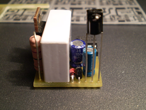
This photo is of v1, photos of v2 are pending. I am waiting for official PCBs from the factory.
How this device works is pretty cool, it powers itself from the mains through the load (usually a light bulb but it can also be a resistive heating element). The way it turns the load ON is by short-circuiting its own power supply! You can control it with your own TV remote controller - all you need is 4 spare buttons (usually those used for Teletext so that they don't interfere with normal TV usage). If you can't spare 4 buttons you can teach the device just 2 buttons, but in this case you either loose the dimming functionality - you can only turn the light on and off, or you loose the OFF button so you would need to dim-down to level 0 in order to turn the lights off. It recognizes two IR protocols: NEC and RC5 (mostly used in the world).
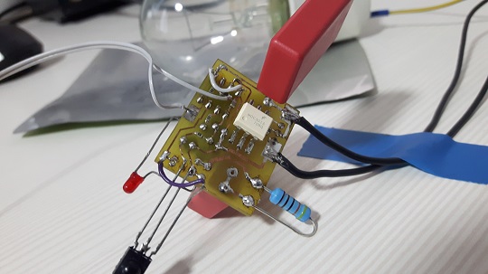
IR Light Dimmer v2 under development - test PCB
Transformerless power supply
The device is powered from the mains voltage using capacitive power supply. You should read all about it on this link: http://www.designercircuits.com/DesignNote1a.pdf and also this link: http://ww1.microchip.com/downloads/en/AppNotes/00954A.pdf
Stand-By (lights Off)
The device powers itself from the mains voltage, through the resistive load (light bulb). It consumes very little power (< 5mA) so the light bulb does not glow during stand-by. The main consumer is the TSOP IR receiver, but you can also use low-power TSOPs such as TSOP38238 if you want to bring this down to under 1mA. In this state, PIC microcontroller is waiting for IR signal from TSOP or a press from the wall switch. Please bear in mind that wall switch must no longer be a classical on/off switch - it must be replaced with a push-button switch that closes the contacts only while you keep pressing it.
In this state the triac is not fired and nothing special happens.
On-State (lights ON or Dimmed)
If a wall switch is pressed or appropriate IR signal is received from the remote, the light bulb will turn ON. Turning the light bulb ON is accomplished by firing the Triac when mains voltage cross the zero point. This is detected with the zero-crossing detector formed with R3 and C6. If we trigger the Triac right after the "zero" has been detected it will turn the lights ON at full intensity. If we delay the Triac firing by some time we can effectively perform dimming as the voltage that appears at the output is smaller than the supply voltage. You can read the app note from ST here: http://www.mouser.com/catalog/specsheets/stevalill004v1.pdf (serial-dimmer such as this one can be found starting from page 16). This app note also contains calculations for the transformerless power supply - so check it out as well!
If we look at the circuit schematics - the power supply part, we can see that when Triac starts conducting it short-circuits our transformerless power supply. At this point entire circuit is powered from capacitor C3. It should be large enough to keep enough power for TSOP (~5mA), PIC (< 1mA) and MOC3023 (~5mA but only for a few microseconds) so don't be shy to use larger-valued capacitor here, such as 220uF/330uF/470uF. If we keep the light turned ON at full brightness it will eventually discharge the C3 completely and restart the PIC microcontroller. This is why we actually never turn the lights ON at full brightness - we actually delay Triac firing a little to "steal" just enough energy to keep our C3 charged. So 100\% is actually more like 99\%. You will see this waveform bellow.
Heating of R1 resistor
One problem with this device is possible heating of the R1 resistor. It is naturally there to prevent the inrush current that might destroy capacitor C1. When the device turns light at full brightness the waveform looks something like this (mind the power-stealing delay so we can keep C3 charged).
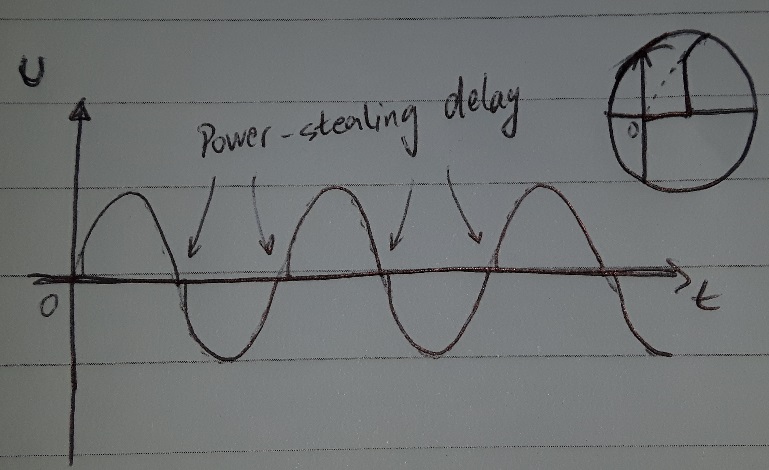
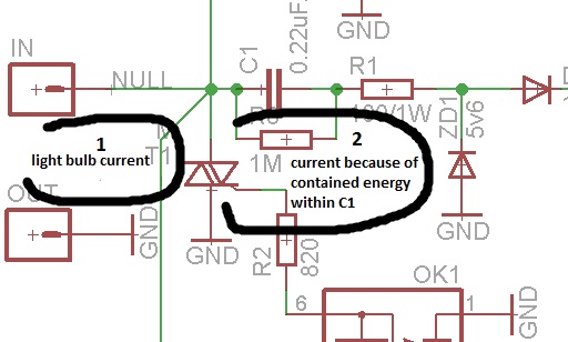
During the power stealing delay the capacitor C1 in the transformerless power supply keeps small amounts of energy and at low voltage so when Triac short-circuits the C1 through R1 and Zener diode ZD1 all that energy is dissipated on resistor R1. Luckily there is not much of it so R1 does not even get warm. The problems start arising when energy stored in C1 is significant such as when the device is dimming the light bulb:
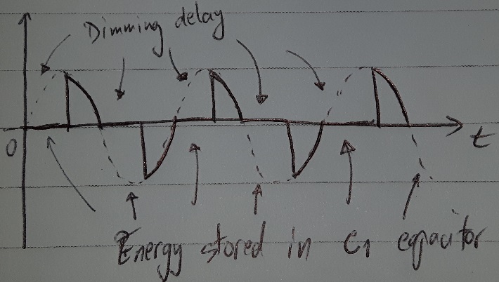
As we can see from the diagram, the amount of energy in C1 is something that requires our attention. When Triac fires all that is dissipated on our poor R1 so it must handle that power. Larger values of resistance for R1 will dissipate more heat but C1 will be much more happy, and lower values of resistance for R1 means less heat but C1 will start buzzing like crazy because now it must handle all that power - it has to go somewhere.
The answer is to use C1 with smaller capacitance (so it can't hold too much energy, but just enough to supply our device) and to use the right value for R1 so that C1 does not ring like a Piezzo crystal (too much). I found that using R1 with 220-680 ohms works for my capacitor 0.22uF (does not ring too much and resistor does not heat up as much). This is for 220V/50Hz that I tested.
EMI (EMC) Notice
This device (as presented here) is not compatible with EMC standards (or any other standards regarding EMI). It is missing a CLC filter which you can build (and you should). The filter consists of three components: two capacitors and a coil. If you are interested, see page 19 of this document: http://www.mouser.com/catalog/specsheets/stevalill004v1.pdf
User Manual
After properly connecting the dimmer and powering it up, you need to program IR codes of your remote controller.
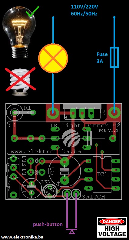
Here is how to perform programming:
Hold the wall push-button for 11 sec so that dimmer can enter programming mode. After those 11 sec, LED will start to blink fast, and light will dim to third (3.) level. Now you have 11 sec to complete the programming sequence:
- Press the first button on your remote that will increase light level or turn on the light when it is turned off (ON/UP)
- Press the second button on your remote that will be used to decrease the light level (DOWN)
- Press the third button that will be used for activating/deactivating sleep mode (SLEEP)
- Finally, press the fourth button that will be used to turn off light completely (OFF)
During programming, both the light bulb and LED will blink to confirm IR code reception. If your remote control does not have all 4 buttons that you can use, you can repeat previous button but that will cancel out some features. For example, if your remote has only two buttons (A and B), and if during programming you press: A A A B, that means that key A will be used for ON/UP function, and key B will be used to completely turn off the light. If you choose combination A B B B, it means that the key A will be again used for ON/UP function, and key B will be used to decrease light level (it will also turn the light off completely in 10 button presses - until zero level).
Programming notice: If during programming, you notice that LED blinks even when you don't press any buttons on your remote control, it is probably because you used TSOP11xx receiver module. In that case, you will probably not be able to program your dimmer properly so replace it with the ones recommended in schematics.
If you are planning to use your TV's remote controller, you should probably choose those teletext buttons: red, green, yellow and blue to avoid, for example, switching channels when operating the dimmer.
Sleep timer
Sleep timer can be activated by a bit longer wall-pushbutton press, more than 1.8 sec to be precise, or by pressing the appropriate button on the remote controller. Sleep timer cancellation is accomplished just like the activation. It is possible to increase/decrease the light level when sleep timer is active. Dimmer will automatically set the light level to six (6) when entering the sleep mode, but only if previous level was greater than 6.
Author (sent by): Trax
Download counter: 2,164
Rating: 


 (3.02, votes 1545)
Date: 02-01-2017
Lokalna verzija ove stranice: IR dimmer svjetla v2
Tags: 110v, 220v, 50hz, 60hz, dimmer, ir, light, microchip, pic12f629, pic12f675, tsop. +add your tag
Hi, I do not think that other triacs will work properly. Maybe it is time to redesign the
circuit!
IP: 217.75.194.149
Dear friend, TIC206 is not available, Please let me know can I use BT136 or BTA016 instead
IP: n/a
dear sir .
thank you for this great project
can you please help me to modefing this project so I can use it to dimming a 5mm LED instead of
AC bulb.
regards
IP: n/a
I built and tested for 220V 50Hz. Works great. Thanks for the source code too! Looking forward
to purchase PCBs once they become available. Great work as usual...
IP: 89.146.142.217
You can log-in on forum link: Login page. After logging-in, return to this page and click refresh in your browser.