comment [34]
- From trax on 04-07-2016 at 19:43:50
I added the assembly instructions (actually just the component placement plans) in the article
above - look for an UPDATE 2016-07-04 in the text. If you need more help let me know!
IP: n/a
Inductive Loop Detector works by detecting an inductance change in wire loop (coil) that is buried in road. It does that by measuring the frequency of the internal oscillator which powers the mentioned coil. When a metallic object moves over the coil it changes its inductance and that in turn changes the oscillator frequency which is measured by the microcontroller. It is used for vehicle access control at door and barrier controls, for monitoring the occupancy and for vehicle counting in parking garages, for traffic light installations and traffic controllers, for direction and speed detection of vehicle traffic (if dual channel version is used), in car-wash plants, etc.
NOTE: Perhaps you are looking for Dual Channel version of Inductive Loop Detector.
Two versions of this device were made: v2.0 and v2.1. Version v2.0 had TPS5405 SMPS buck converter IC but that turned out to be a bad choice because of it's low maximum input voltage and dynamic switching frequency change (special feature of TPS5405) which interfered with our loop oscillator in some cases. Therefore, here is a better version v2.1 that uses LM2596 IC.
UPDATE 2015-10-25: PCBs are available for purchase here: http://www.elecrow.com/inductive-loop-vehicle-detector-v21-pcb-board-p-1458.html
UPDATE 2016-07-04: PCB component placement is here: top side, bottom side.
UPDATE 2016-07-26: Where to get the BEL-FUSE transformer core: http://www.ebay.com/itm/BEL-Fuse-Inc-ADSL-Transformer-S560-6600-F5/160665292582. After ordering you will need to disassemble the transformer and re-wind the primary and the secondary winding. To disassemble, use heat-gun to heat the core so that glue deactivates. Gently separate two parts of the transformer core using two pliers. After that, remove original wiring from the bobin, rewind 50 windings to primary and 50 to secondary. Glue the transformer back and you are all set. Remaining parts are not critical and can be ordered from eBay and Tayda Electronics webshop. Here are few other links to get you going: LM2596 with coil and Schottky diode, Neon bulbs, Songle 5V relays, BSS123 transistors, and so on...
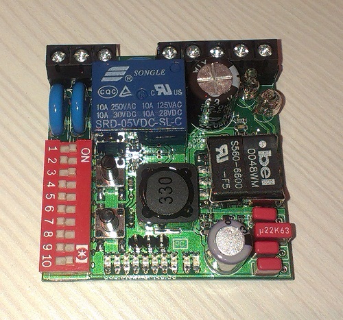
ILD v2.1
Specifications
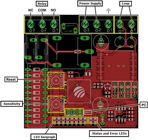
Pinout of electronics (note: this is actually for version 2.0 but pinout is the same for this version 2.1)
Hardware
Main component of this device is Colpitts oscillator which consists of just one transistor and few passive components. Frequency of oscillation is determined by number of coil windings - inductance and capacitors in oscillator circuit - capacitance, which can be changed with DIP switches. Wire loop (coil) is isolated from sensor electronics with 1:1 ratio isolation transformer. Transformer that I used in this project is from an old ADSL modem but rewound to 1:1 ratio. Transformer is not really critical, but RM5 core is your best choice. Note: You can build this oscillator without a transformer too! Common frequency range used for these detectors is from 30 kHz to 150 kHz.
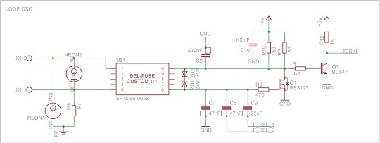
Loop oscillator
Oscillator is connected to PIC16F877A microcontroller's RA4/T0CKI input via NPN transistor. Microcontroller is measuring the frequency of oscillations and determines whether the detection has occurred or not. There is a LED bargraph display that is used to show and set current detection sensitivity level and it also displays current level of detection as metalic objects approach the coil.
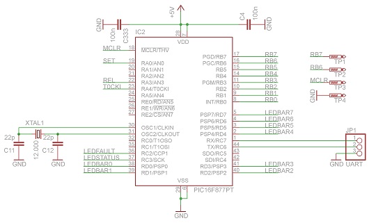
MCU PIC16F877A (entire schematics can be downloaded by clicking on the red download button bellow)
Electronics are powered by LM2596 SMPS step-down (buck) converter IC. It has a maximum input voltage of 40V DC which is perfect in case our electronics are powered from alternating ~24V because after rectifying we end up with 34V DC. LM2596 can provide 2A of current which is actually an overkill for this sensor, but I went for it since it is extra cheap and easy to order from eBay.
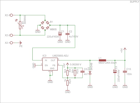
Voltage regulator LM2596
Firmware
As this project is all about measuring the frequency (30-150 kHz) we need to choose the best method of measurement for this application. We can choose from two methods of measurement: frequency measuring (direct method) by using "gate time" or period measurement where we count pulses and work with that value.
The only suitable method for this application is actually the "period measurement". Impulses from oscillator are connected to RA4/T0CKI input pin of microcontroller, and on every overflow of TIMER0 counter I simply read the value of counter TIMER1. TIMER1 is configured as a free counter and its value is incremented with every internal clock pulse (Fosc/4). TIMER0 is configured and prescaled so that during normal operation of sensor electronics TIMER1 must never overflow over it's maximum value (65535). Value of TIMER1 is manually cleared to zero on every TIMER0 counter overflow, so it starts counting from 0 every time.
After powering up the device, oscillator starts to oscillate and microcontroller performs a startup measurement which is reported on yellow LED by blinking in 10kHz steps. Initial setup of TIMER0 is: prescaler=1:2, reloader=0. Reloader is a preset initial value which is loaded into TIMER0 after each overflow in order to speed it up. Prescaler tells us that the value of TIMER0 will increase by 1 on each 2 pulses that arrive from the oscillator. This means that overflow of TIMER0 will occur after 512 pulses which in turn means that by using MCU Fosc=12 (actually 12/4 MHz) and at loop oscillator frequency of 30 kHz TIMER0 will always overflow when value of TIMER1 increases to 51200. If we calculate the resolution at these values we can see that it is 0.58 Hz which is excellent. Under these same conditions but at loop oscillator frequency of 140 kHz value that TIMER1 value would be 10971 and resolution would be 12.76 Hz which is pretty bad.
It would be best if we could somehow fix value of TIMER1 counter to around 53000 at any given loop oscillator frequency. This can actually be done by prescaling the TIMER0 and preloading it with some initial values. This means that after microcontroller starts and performs initial measurement, it can figure out the best values for TIMER0 prescaller and reloader so that TIMER1 gets around 53000 where it will have best resolution and in turn have best sensitivity. Value for TIMER1 has been chosen to 53000 because during normal operation no metallic object can increase it that much so that it causes an overflow. In case it does overflow, the microcontroller will re-adjust TIMER0 prescaler and reloader values so it gets back to around 53000.
By using this method we ensure that device has the best sensitivity at any loop oscillator frequency.
After the initial calibration is finished, sensor remembers current value of TIMER1 and uses it as baseline value to compare with any following measurement. If frequency change that crosses selected threshold is detected, the sensor goes into "detect" state. Later when frequency changes back to the baseline value the sensor goes back to "idle" state.
During normal operation sensor constantly re-adjusts the baseline frequency value because it tends to drift with temperature changes of electronics and the wire loop itself.
DIP Switches
There are 10 DIP switches to configure the operation of sensor electronics. When the switch is in left-hand position it means that it is turned "off", right-hand position means that switch is turned "on".
Sensor should be reset after making any DIP switch changes!
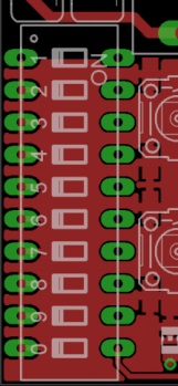
DIP switches
| DIP 1 | Signal Filtering (B) |
| DIP 2 | Signal Filtering (A) |
| DIP 3 | Presence Selection (B) |
| DIP 4 | Presence Selection (A) |
| DIP 5 | ASB (on, off) |
| DIP 6 | Relay Pulse Duration (on = 500 ms, off = 100 ms) |
| DIP 7 | Relay Pulse Type (on = on loop leave, off = on loop enter) |
| DIP 8 | Relay Type (on = presence, off = pulse) |
| DIP 9 | Frequency Selection (B) |
| DIP 0 | Frequency Selection (A) |
Signal Filtering
There are 2 DIP switches for selecting 4 filtering stages: DIP 1 i DIP 2. Filtering stages are described in detail in PDF user manual.
Presence Selection
If this option (DIP 3 and DIP 4) is selected to infinity, the "detect" state will remain as long as there is a vehicle above the loop. One possible problem of using this option is that in "detect" state sensor electronics do not track and compensate for frequency drift. In extreme situations this can either cause false detect when vehicle finally leaves the loop (in this case device must be reset manually), or somewhat slower response time of further detections until device completes positive frequency drift compensation.
ASB - automatic sensitivity booster
DIP 5 - This option increases sensor sensitivity to maximum upon detection. This is usually used to detect trucks and vehicles with trailers if sensor is not already configured to maximum sensitivity. If sensor is already configured to maximum sensitivity, this option is ignored.
Relay Pulse Duration
DIP 6 - This option selects the duration of relay pulse in case Relay Pulse Mode is selected. When the DIP switch is at "on" position the pulse lasts ~ 500 ms, if the switch is at "off" position the pulse lasts ~ 100 ms.
Relay Pulse Type
DIP 7 - In case Relay Pulse Mode is selected; this option defines whether the pulse will occur when vehicle approaches the loop or leaves the loop. When DIP switch is at “on” position then the pulse will occur when vehicle leaves the loop, otherwise the pulse occurs when vehicle arrives on the loop.
Relay Mode
DIP 8 - This option selects Relay Mode. If the switch is at "off" position then relay will be activated for as long as there is a detection. Otherwise relay will just send out the pulse which is defined by DIP 6 and DIP 7.
Frequency Selection
Frequency of loop oscillator is primarily defined by the wire loop geometry and the number of windings. In order to slightly change the frequency of the loop oscillator there are two DIP switches DIP 0 and DIP 9.
Loop oscillator frequency is displayed on yellow status LED after the device is reset. LED will blink in steps of 10 kHz. Example: if LED blinks 7 times it means that the frequency of loop is from 70 kHz to 79 kHz.
Sensor should be reset after making any frequency adjustments!
PC Configurator
All working parameters of the sensor can be fine-tuned by using supplied PC application.
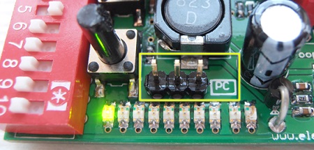
PC configuration UART (TTL!) port
Explanation of parameters
Sensitivity - "Osjetljivost"
When metallic object approaches the loop it changes its inductance which in turn changes the oscillator frequency. Oscillator frequency is internally represented by number that has range of 1 to 255. Smaller metallic objects (for example bicycles) make smaller changes to this number while larger objects (such as cars) make bigger changes. Sensitivity has two thresholds: detection threshold which represents the number that the object must change inside the MCU in order to declare detection, and un-detection threshold which represents the number that is required in order for it to remain in "detect" state. Un-detection threshold is always smaller than the detection threshold and is usually 1/2 or 1/3 of the detection threshold.
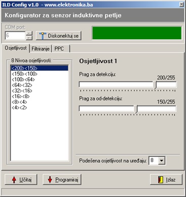
Sensitivity
Programmed values for each sensitivity level remain in sensor's internal EEPROM memory and can be selected with the Sensitivity Button while device is operating.
Signal Filtering - "Filtriranje"
Filtering is very important part of sensors internal operation. There are 4 filtering levels that can be selected and fine-tuned using this PC configurator app. Parameters that define filtering levels are:
Note: Number used for negative drift compensation can also be used for positive drift compensation. Parameter used for positive drift compensation should be equal to or smaller than the number used for negative drift compensation.
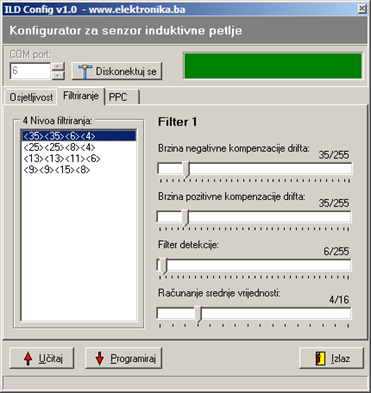
Filtering
There are 4 levels of filtering that can be programmed into the sensor and later selected by the appropriate DIP switches.
PPC (permanent presence canceller) - Presence Selection
Values for Presence Selection can also be fine-tuned. Detailed instructions about this can be found in PDF user manual.
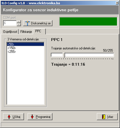
PPC
Note: All files required to build this device (schematics and PIC firmware) are available by clicking on the red download button bellow.
Video of sensor in use (this is video of version v2.0)
Testing on the desk
Outdoor testing
Photos of sensor (note: this is PCB version v2.0)
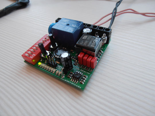
Device in idle state showing current sensitivity level (maximum)
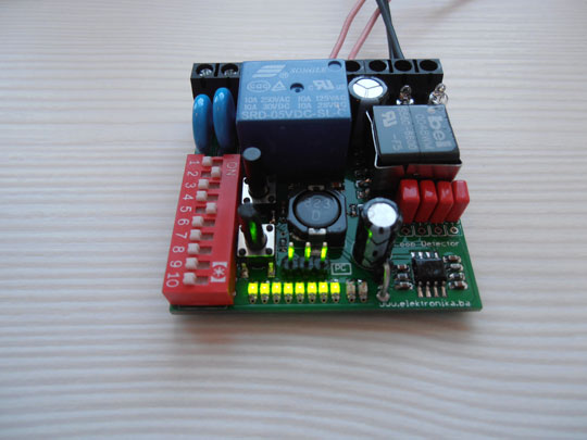
Device in "detect" state
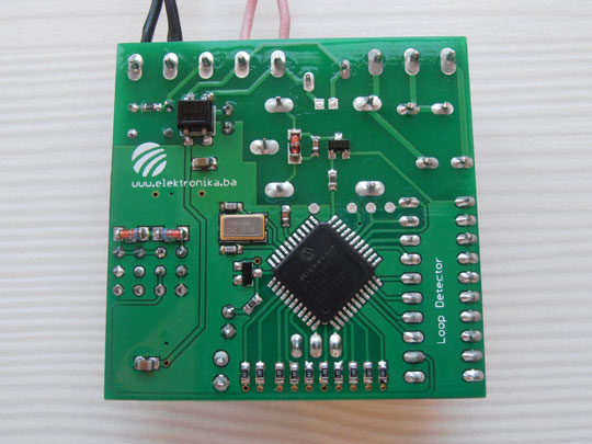
Bottom PCB side where MCU is located
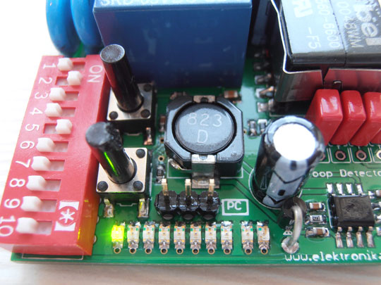
Close-up of top PCB side
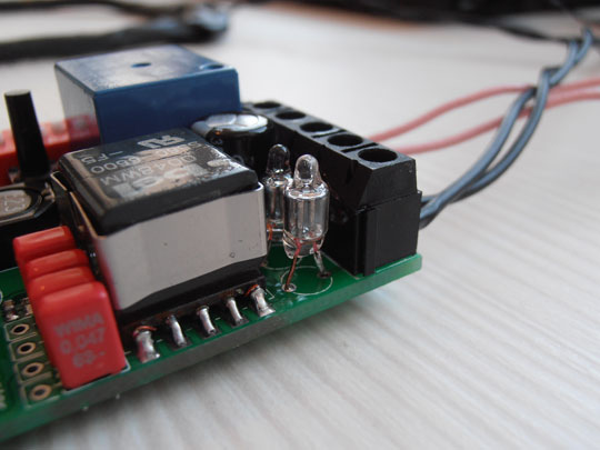
Gas discharge tubes and 1:1 isolation transformer
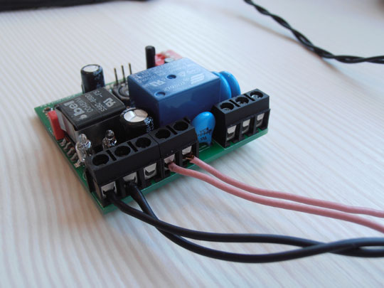
Connectors
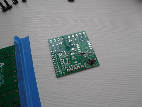
Soldering top side
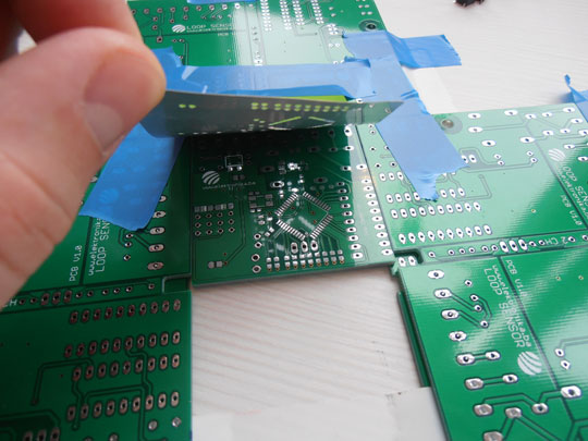
DIY stencil from a fizzy drink can
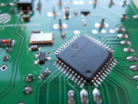
Close-up of bottom PCB side with MCU and 12.000 MHz crystal
Author (sent by): Trax
Download counter: 3,890
Rating: 


 (3.03, votes 3621)
Date: 19-02-2014
Lokalna verzija ove stranice: Induktivna petlja za detekciju vozila v2.1
Tags: detector, ild, inductive, loop, oscillator, pic16f877a, sensor, vehicle. +add your tag
You mentioned that its possible to do this circuit without a transformer, would I just jumper
across the transformer pads instead?
IP: 66.169.111.180
I added the assembly instructions (actually just the component placement plans) in the article
above - look for an UPDATE 2016-07-04 in the text. If you need more help let me know!
IP: n/a
Ok, I can send it to you on monday. I am on vacation currently. Regards
IP: 93.137.14.37
I already have the board, so the list of everything else and assembly instructions would be
most excellent.
IP: 68.45.42.131
Yes, it is just $7 for the PCB. I can send you the list of components and the assembly
instructions but I can't provide you with the KIT. You can order all remaining components from
eBay. It should not be a problem...
IP: 93.137.14.37
I ordered the board, only to realize that it was only the board that I would receive, not the
entire assembly. Can you provide the bill of materials for the complete build?
IP: 68.45.49.174
PCBs are now available for purchase here:
http://www.elecrow.com/inductive-loop-vehicle-detector-v21-p-1458.html
IP: n/a
Yes, the PCBs will be available soon for sale! Look for it here...
IP: n/a
hi,
Im a student in college and for my project I need some sort of inductive loop vehicle
detector. I really like your PCB and I was wondering would I be able to purchase a few of them
please.
kind regards
pavel
IP: 37.228.243.134
hey, is there any chance I can get pcbs for this? I'm grateful that the schematics and binary
are available, but I don't think I'd do a good job at recreating the pcb... so I was wondering
if we could come to an arrangement so I could buy them off you or escrow the pcb files to a
small batch manufacturer and let me run off a few. I would like 2 and really like 4 so I have 2
backups. If its at all possible let me know what you'd like to arrange. I'd love to get these
assembled before the end of year
Thanks :)
IP: 203.59.228.230
You can log-in on forum link: Login page. After logging-in, return to this page and click refresh in your browser.