comment [26]
- From trax on 27-05-2013 at 15:54:10
Da, to je to! Tako ih ja programiram kada ih ne mogu ubosti u programator. Samo pazi da sve
spojis kako treba, i prvo spoji GND prije ostalih pinova.
IP: n/a
I needed a good LC meter for my one of my next projects so I went and built the famous LC meter by Phil Rice. This LC meter design is pretty old but since it is a perfectly good device there was no need to design/build/debug one of my own. So, I just changed the original firmware a bit and added few electronic goodies to it to make it more compact.
UPDATE: Project is on HackedGadgets, ...and now also on Hack-a-Day!
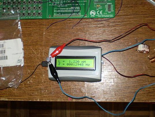
Measuring a 1200uH (122) coil from Coilcraft
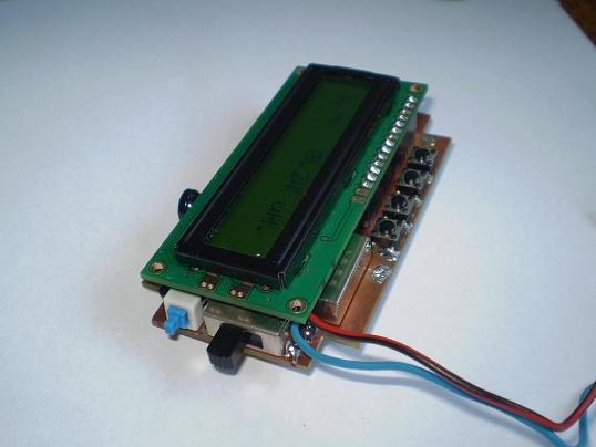
LC meter - SMD
Power Supply
I wanted to fit it in this project box that I had laying around for some time and I also wanted it to be battery powered. There was no way that I could fit 9V battery in this project box along side with all the electronics, so I figured I could add a tiny 3.6V Li-Ion battery that I also had... laying around.
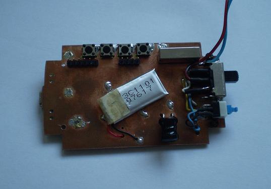
Tiny Li-Ion battery
It is a 135mAh one from a broken Bluetooth headset. After having no luck in finding the appropriate 2x16 or 1x16 LCD that works at 3.6V I decided to incorporate a 5V voltage booster that will do the trick. For this purpose I selected TPS61222 power booster from Texas Instruments. This little (extremely little) device is very good and it requires just a coil and two capacitors to operate.
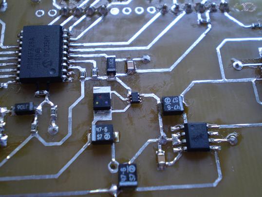
TPS61222 - the smallest IC in the center of the picture and MAX1811 on the right
Now, because there is a Li-Ion battery in the device I needed a way to charge it properly. This is done by MAX1811 Li-Ion charger IC from Maxim. Later on, by placing a small USB connector on board, all power supply & charging problems were solved.
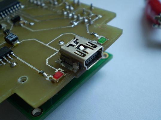
USB connector for charging the Li-Ion battery
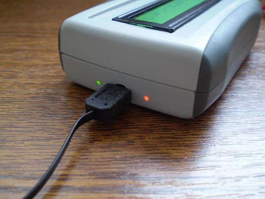
Charger (USB) connected - GREEN, Charging battery - RED
Firmware modifications
No critical firmware modifications were made. All calculations are performed as they were in the original firmware. Only a few small changes were made such as: PORTB pinout re-arranged for LCD display, second line of display constantly shows oscillator frequency, LC meter is automatically re-calibrated ("zeroed") when switching from L to C and the other way around.
Zeroing the meter
This meter has a strange "zeroing" function. After turning it on it is necessary to "zero" it by resetting the microcontroller. It seams that it is not the same when you turn the device off and back on for less than a second and resetting the PIC. Why this happens - it is still a question mark above my head. I noticed this phenomenon after building the device and obviously I didn't plan to put a "zero" button on the front panel. This was fixed by modifying the firmware in a way that re-calibration is executed after changing the measurement mode from L<->C and C<->L but with a small delay, of ~700ms after flipping the mode-switch. The re-calibration is actually a program reset - it starts from the beginning just as if it was reset by hardware. This "zeroes" the meter almost identically as it is "zeroed" by hardware microcontroller reset, so it is all good.
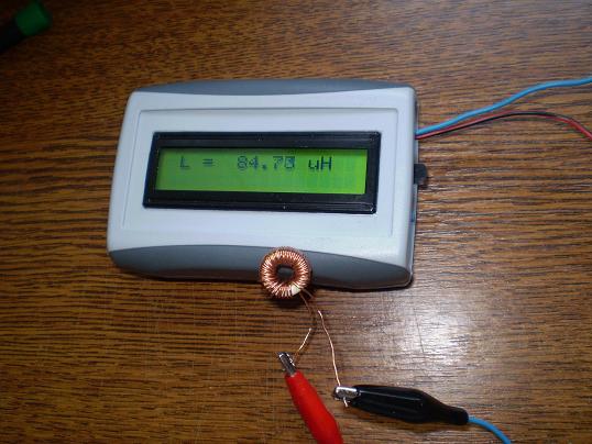
Measuring unknown inductance 1 (frequency hidden)
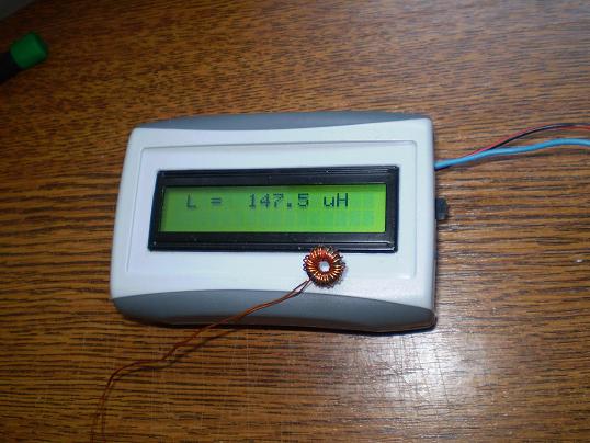
Measuring unknown inductance 2 (frequency hidden)
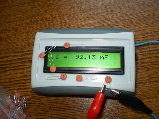
Measuring a 100nF capacitor (frequency hidden) - this was when it wasn't calibrated properly
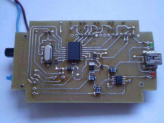
Bottom PCB side
Schematics & firmware
Schematic diagram is identical to the original one, I only added MAX1811 and TPS61222. The SCH and PCB (Eagle Layout) can be downloaded below (the red download button). Modified firmware can also be downloaded from here if you wish to build this Li-Ion battery powered version (firmware is written in assembler).
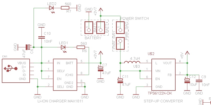
Addition to original schematics: MAX1811 i TPS61222
Original LC meter sources
- http://sites.google.com/site/vk3bhr/home/index2-html
- http://www.marc.org.au/index.html
- http://ironbark.bendigo.latrobe.edu.au/~rice/lc/index2.html
Author (sent by): Trax
Download counter: 7,864
Rating: 

 (2.97, votes 4478)
Date: 16-09-2011
Lokalna verzija ove stranice: LC metar sa PIC16F628A
Tags: capacitance, inductance, lc, lithium, max1811, meter, pic16f628, pic16f628a, tps61222, usb. +add your tag
A što je sa Low-Voltage Programming trebam li na to pažnju obraćati kod ICSP-a
IP: n/a
Da, to je to! Tako ih ja programiram kada ih ne mogu ubosti u programator. Samo pazi da sve
spojis kako treba, i prvo spoji GND prije ostalih pinova.
IP: n/a
Znači samo da zalemim tih 5 pinova direktno na žice spojim ih na programator i loadujem
program, da li na još šta moram paziti ?
IP: n/a
Ja sam ga programirao sa EasyPIC3 tako sto sam na sam chip zalemio zice i te zice onda utaknuo
u EasyPIC3 plocu u podnozje za DIP 18. Posto chip u tom slucaju nije pod napajanjem (nije
zalemljen u LC metru) moraces mu spojiti i Vcc pin. Znaci spajas: GND, VCC, MCLR, RB6 i RB7.
Svaki na svoje mjesto u podnozju na programatoru. Raspored pinova kod ovog kucista je identican
kao i za DIP 18 (veliki PIC).
IP: n/a
Da bi isprogramirao ovaj kontroler, trebas na programator spojiti njegove pinove i to: GND,
MCLR, RB6 i RB7. Koji programator koristis?
IP: n/a
Je li mi može netko dati uputstvo za ICSP jer nikako drugačije ne mogu programirati ovaj
kontroler
IP: n/a
Hello, to remove measuring capacitance, just follow where wires go when switch is connected for
capacitance measurement, and remove all components that are not used for inductance
measurement. Simple! I don't know how accurate it will be, do you have another L-meter to
compare results?
IP: n/a
Hello, I am currently doing a project which involves measuring very low inductance (ranging
from 90uH to 95uH) and I believe this device will work perfectly for this purpose. Do you
think it it possible to have accurate measures of this and would you recommend me any changes
for not using the capacitance measuring part?
IP: 146.155.157.13
Može li mi netko dati popis svih dijelova treba mi jer sam ovaj projekt uzeo za završni rad
unaprijed hvala
IP: n/a
You can log-in on forum link: Login page. After logging-in, return to this page and click refresh in your browser.