comment [60]
- From Pete on 17-11-2016 at 14:25:09
Hi can you tell me what software I need to program, is there a guid or howto.
Thanks.
IP: 147.188.101.148
This clock is designed to be easy-to-build, with all usual parts - except the tubes of course, and modular - meaning you can put any kind of Nixie tube on the top "shield" board and completely redesign it's look. If you don't fancy Nixie tubes (looser!), you can multiplex other kind of display.
Clock works at voltages from 7.5V to about 14V and consumes around 200mA. The PCBs are 10cm x 3cm, so pretty small. Beware that it generates high voltages of around 200V so don't touch anything while it is operating. It shocked me few times and I dropped the clock on the table (no damage done to me or the clock).
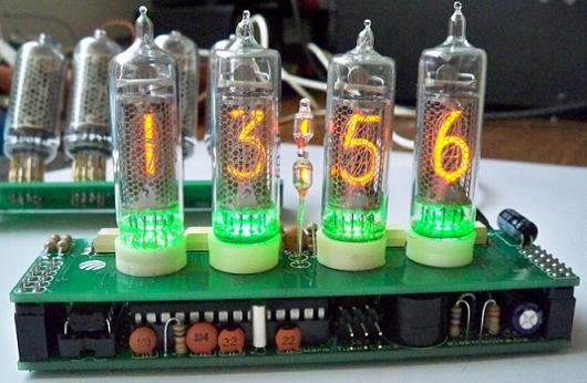
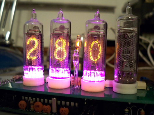
The shield board has 4 RGB LEDs under the Nixies that can be turned off if you don't like how it looks. It shows time, full date and temperature. There is also a "candle mode" in which all four tubes lit up and simulate the flickering of candles. This looks pretty cool in dark room and you can even put it on the dining table for a bit of romance.
All project files are available for download by clicking on the red download button below (open source hardware).
UPDATE: Project is on Hack-a-Day, ...and now also on HackedGadgets, and on TubeClockDB, whoho :-) !
UPDATE 6/2/2011: New version of project!
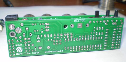
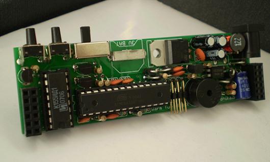
So here are the clock's options:
1. time display
2. date display
3. temperature display
4. configurable times of showing for all of above (for example, the clock can display time for 20 seconds, and move to next thing to display: date, temperature or both and go back to time. It can even be set to display only the temperature)
5. configurable Nixie tube brightness
6. configurable color of bottom RGB LEDs that blink at 1/2 Hz rate (or even turned off)
7. the "temperature color blender" option that displays blue color at lower temperatures, red at high temperatures and mixes these two colors between these extremes (or even turned off)
8. configurable color of bottom RGB LEDs while displaying date (or even turned off)
9. fading tubes while showing the date for better understanding of what is on display (DD.MM and YYYY)
10. Nixie tube saver option - this option turns off Nixie tubes at defined "sleep" time and turns them back on at defined "wakeup" time (for example, the clock can be configured to shutdown at 23:30 and turn back on at 07:30 in the morning) in order to prolong the life of tubes
11. alarm function with user-configurable melody with snooze function
12. user configurable snooze length with automatic snoozing so that the clock doesn't ring constantly forever if forgotten about
13. Nixie tube cross-fading with configurable fade speed
14. the famous "candle mode" for the romantic "touch"
15. cathode anti-poisoning on every 15 minutes
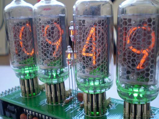
Few notes about the design
After seeing a few RGB LED projects around the web with the TLC5940 IC I decided to give it a try by using it to multiplex the Nixie tubes and drive RGB LEDs at the same time. I chose the SMD version TLC59401 and after some trial an error I managed to make it work, and it works great. The interrupt routine inside AVR sends new data to TLC59401 in a configurable periods of time (refresh rate). This rate is different for each model of Nixie tube, so for IN-16 tubes slower rate is required than it is for the IN-8 tubes. Advantage of using the TLC IC to multiplex Nixies is that it is possible to adjust each Nixie tube with a different brightness quite easily.
The power booster is just like the one used in the Ice Tube clock but with feedback option (I can safely say that this clock is pretty much inspired by the cool Ice Tube clock). The AVR has no clue of what duty cycle it must set for the PWM output to generate the required voltage, so it reads back the voltage produced on the HV output and increments the duty cycle until required voltage is produced. This way the value of coil in booster circuit is not firmly defined.
Power supply unit (5V)
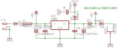
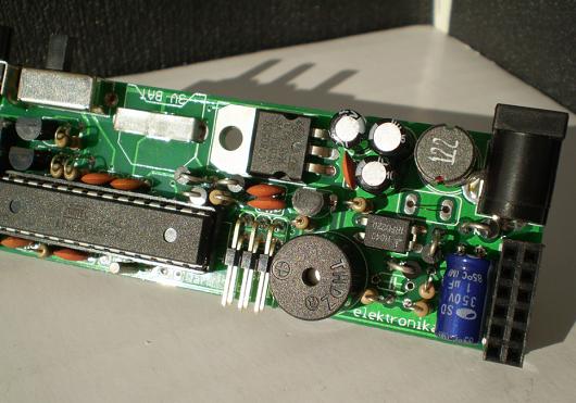
The power supply unit has a self-resettable fuse that will cut the power if things get freaky and restore the power once it cools down. The PSU has three outputs +9V, +5V/1 and +5V. The +9V is used in HV voltage booster section and is actually whatever you supply the clock with (from the power source), the +5V/1 is used to power everything on-board except the AVR. The AVR is powered by +5V source which is battery backed-up, meaning that when power gets lost the AVR will continue working on 3V button cell battery. These two "separated" 5V power supplies are done by using three 1N5817 high-speed diodes.
HV voltage booster
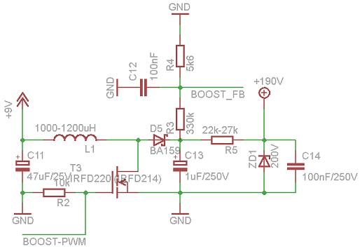
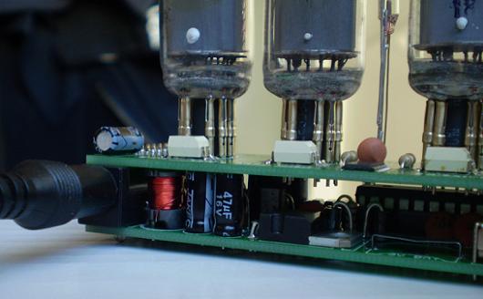
This circuit is a basic boost converter (step-up converter) device just like the one you've read about here http://en.wikipedia.org/wiki/Boost_converter. The coil used in this circuit is 1200uH (any value around 1000-1200uH can be used) from Coilcraft. The PWM frequency used for booster MOSFET switching is 31.250 kHz with different duty cycles for different output voltages. The high voltage builds up in the storage capacitor C13 and is being measured by AVR through the voltage divider circuit formed by R3 and R4. Nixie tubes get their needed high voltage (the current actually) through a current limiting resistor R5 and they are protected with Zener diode ZD1 200V. The high voltage is further being filtered with capacitor C14 which is actually not mandatory (I never soldered it and the clock works like clockwork). The Zener diode is optional but it is recommended. Any generated voltage higher than ZD1 voltage (200V) will be spent on resistor R5 which will cause it to heat up. If the clock can't produce required voltage upon startup, it will report this by beeping and blinking all LEDs in red color and will stop working (go to sleep). However if it produces over-voltage, it will reduce the voltage to below requested value and report this by blinking all LEDs in orange color, but the clock will continue working. To fix this, another power source with slightly different voltage usually does the trick. If that doesn't work out, another coil should be used.
Nixie cathode driver
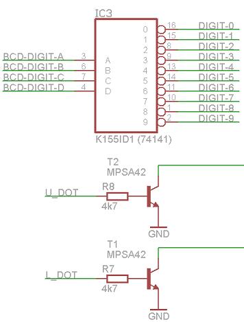
Nixie tubes that show digits have 10 or 11 cathodes for all numbers 0-9 and an optional dot. To save pins on the AVR, a BCD decoder is used. This is not an ordinary BCD decoder because it can withstand high voltages used to power the Nixies. This driver is IC2 K155ID1 which is a 74141 equivalent. It has 10 outputs for 4 BCD inputs. Between two middle Nixies on the top board there are two "colon" neon bulbs (small Nixies) also working on high voltage. These two are "driven" by two NPN high voltage transistors T1 and T2 MPSA42.
Beeper and temperature sensor
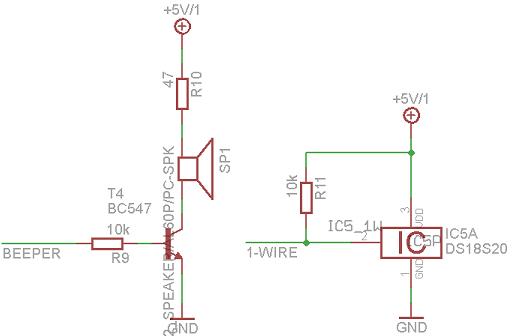
The beeper is a small speaker just like in your PC's mainboard. A piezo speaker can also be used here, but the sound will not be as fuzzy as it is with PC speaker. It is driven with a BC547 NPN transistor and volume is adjusted with R10 resistor. The sound is produced on AVR's pin PB1 (OC1A) by software - not hardware PWM. The alarm sound melody is user-adjustable in wt.h header file.
The temperature sensor is Maxim-IC DS18S20 and is directly connected to AVR's appropriate pin. The 1-wire library used in this project is not interrupt-safe, meaning that the 1-wire data transmission will be interrupted sometimes by ISR routines and will produce invalid temperature readings (00.5 degrees). This can be fixed in the source-code by disabling interrupts in certain parts of the source-code. This, however, I didn't do since it can produce display flickering during temperature readings.
Both the beeper and temperature sensor are supplied by IC2 7805 stabilizer and do not consume any power from the backup battery.
ISP port and buttons/switch
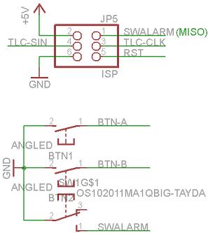
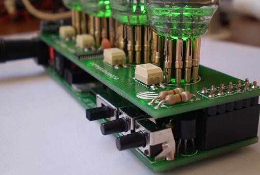
The clock is controlled with just two buttons and a switch. Switch is used to turn on/off the alarm. The buttons are used to request the temperature and date to be shown, enter the settings menu or activate the "candle mode".
The clock can be (re)programmed without taking out the AVR chip with this standard ISP port. Before programming, make sure that the switch SWALARM is turned off (disconnect state). Also make sure to disconnect the programming cable from the ISP connector after programming, or display flickering and "ghosting" effect can be seen on Nixie tubes while clock is working.
ATMEL AVR brain
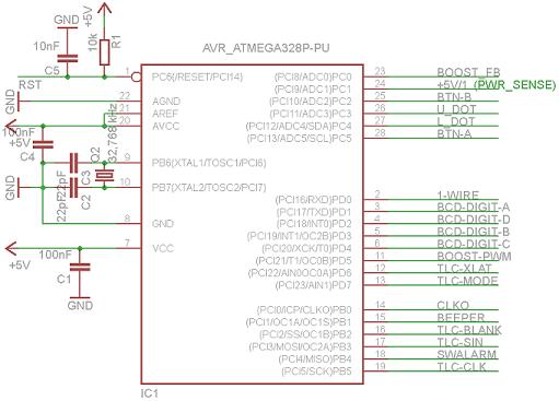
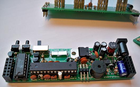
The brain of the clock is ATmega328P AVR microcontroller (the datasheet says it works at low voltages as 1.8V, and this is great because it must continue working on 3V backup battery). The important thing to notice here is the external crystal of 32.768 kHz that is used to clock the internal Timer1. That timer is set with a prescaler of 128 so that it generates interrupt once per every second and that is used for internal RTC. For some reason the AVR doesn't interrupt on every second, but slightly faster (not ideal). So, the capacitors C2 and C3 around the crystal should be adjusted for the smallest error, meaning you should put a variable capacitors here, or experiment with these values to get best (near to ideal) results. You can also use ATmega168 if you strip the source code to bare minimum (not using A/D feedback voltage measurement, and commenting out the "temperature color blender code" would be a good start). Another thing to notice here is the CLKO output of the AVR. Yes, this output is used to export AVR's internal clock signal and is used to clock the TLC59401 on the upper "Nixie shield" board.
Nixie anode & RGB LED driver
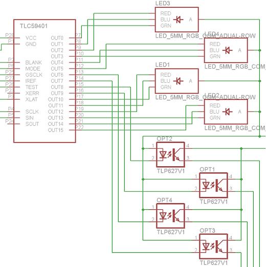
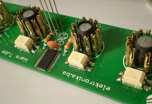
The anode driver for Nixie tubes is made with NPN optocouplers OPT1..OPT4 TLP627. These optocouplers can withstand "Vce" voltages of more than 200V which is required. They are used in "common collector" configuration aka emiter follower / voltage follower because Nixie tubes don't draw much current and this seams efficient. I have seen this kind of usage of NPN optocouplers in other Nixie tube clocks and it works like a charm. When Nixie tubes are displaying numbers, these optocouplers are being switched in high speed providing anode voltage to one Nixie tube at a time. That is called multiplexing. They are switched by the Texas Instrument's excellent IC TLC59401 and on it's remaining 12 outputs (16 in total) there are 4 RGB LEDs with common anode. The interrupt routine in the AVR refreshes the TLC59401 IC all the time thus sending new data to all LEDs and all optocouplers. Driving the TLC59401 IC is pretty easy once you figure out how. There are 7 inputs that require our attention; GSCLK pin - this pin needs to be provided with a constant clock; BLANK pin - on every 4096 impulses of the GSCLK signal it requires a small impulse that will reset it's internal counter; XLAT pin - this pin has to be triggered whenever new data is clocked in (this is done together with the BLANK pin); MODE pin - this tells the IC if the incoming data is Data or Command; SCLK, SIN pins are for sending data over SPI bus. The important thing to note about the TLC59401 is that you must solder the bottom pad to GND. If you fail to do that, the chip will not work properly or at all!
Nixies
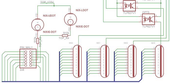
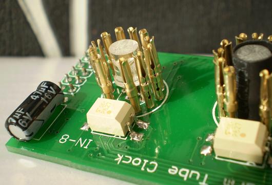
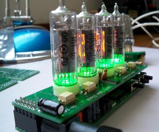
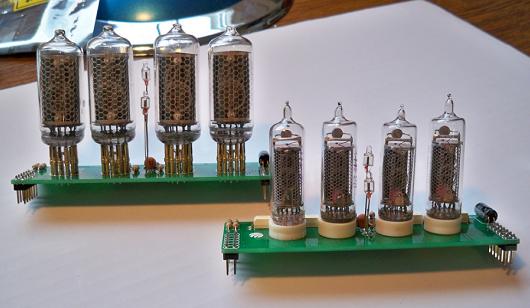
On the upper board (the Nixie shield) there are four Nixie tubes and there are two shield designs for two different Nixie tubes: IN-16 (smaller in size but much more beautiful) and IN-8 (medium sized). Between two middle tubes there are two "dots" or "colons" which are controlled individually so when showing the temperature only upper "dot" is lit, and when showing the date only bottom "dot" is lit. These "dots" are actually a very tiny neon indicator bulbs that you can find in wall sockets, indicator lamps or voltage testers. Luckily they glow in the exact same color as Nixies. Cathodes of all Nixies are connected to the outputs of K155ID1 (74141) and cathodes of "dots" are connected to two NPN transistors MPSA42.
Alarm test and "menu" presentation
Changing some settings on the clock
Introduction and overview of the clock
Nixie Digits - Cross Fading Example
Author (sent by): Trax
Download counter: 40,433
Rating: 

 (2.99, votes 4938)
Date: 17-11-2010
Lokalna verzija ove stranice: Warm tube clock v1 - Nixie sat
Hi Pete, there is a forum discussion on building v2 of the clock. Do not build this v1 - it is
not as accurate. Also, switch the website to english language (on the top right there is
English link). Or visit this URL: http://www.elektronika.ba/800/warm-tube-clock-v2-nixie-clock/
and there you will see a Forum URL.
IP: n/a
Hi can you tell me what software I need to program, is there a guid or howto.
Thanks.
IP: 147.188.101.148
Have you made this version v1 or the new version v2? Please register on forum, so we can
continue the discussion on this topic:
http://www.elektronika.ba/forum/viewtopic.php?f=30&t=10968&p=108225
IP: n/a
Hi! An interesting project. I need help from the author. I made this scheme, but not everything
works. Leds are flashing green lamp always shows 44: XX (xx is all light instead of numbers),
then changed to XX: 1, and nothing changes when you press the button. Maybe there's another
firmware? Give me please.Thanks!
IP: 109.162.120.75
Hi Adam,
I can give you some help. Skype me at bvbernard.
IP: 174.7.80.105
I was also hoping to programthe ATmega328p with an Arduino Uno.
IP: 164.107.188.122
Would someone be willing to walk me through the programming of this?
I am a bit of a beginner here!
I have a mac, but I can boot into windows, I have AVR studio installed on windows as well as
winAVR, I also have avrdude installed on both OSes.
I would really appreciate it.
IP: 140.254.45.40
Hi, I drilled those white spacers with a 7mm drill bit so that LEDs shine directly into the
glass tube.
IP: n/a
Oops. Noticed you are using the CLK0 for GSCLK. Ignore my first question.
IP: 139.142.107.9
You can log-in on forum link: Login page. After logging-in, return to this page and click refresh in your browser.