comment [15]
- From Parac on 18-08-2010 at 14:58:42
A jel to nema plocice za dvo-kanalnu verziju?
IP: 80.65.75.4
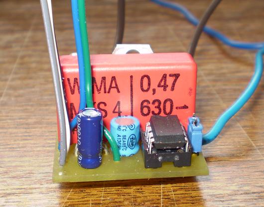
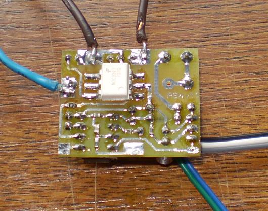
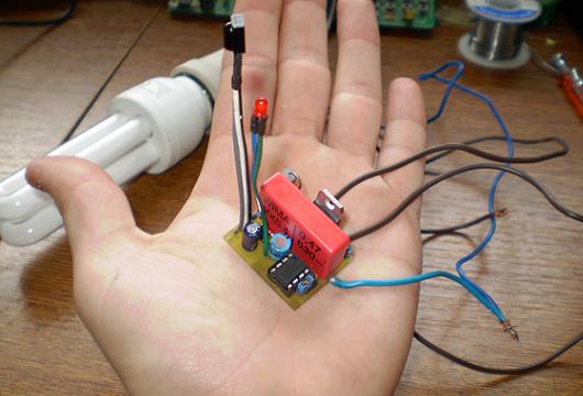
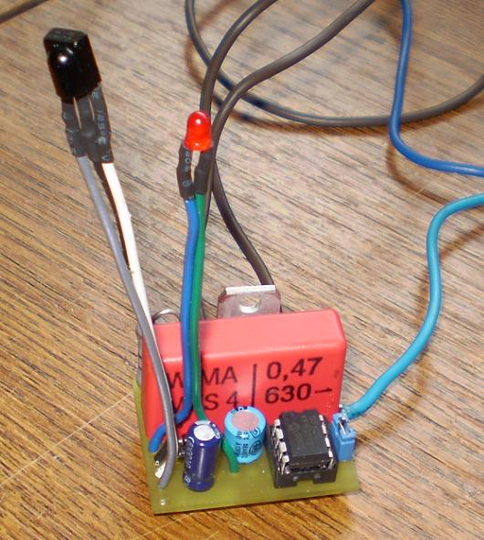
This project is very similar to previous one: IR light dimmer v1. The reason for building this device is primarily because incandescent light bulbs are being widely replaced with fluorescent power-saving ones. So the differences between dimmer and this device are that it has two channels, it can't be used for light dimming and it can control those power saving fluo-bulbs which have internal electronics/converters. The controlling element is solid state relay (SSR) which consists of opto-triac MOC3043 (MOC3042) and a triac (ie.: BTA16, BTA08, ...). This combination enables us to turn ON/OFF all kinds of appliances (motors, lights, heaters, boilers, PC...). In case you are having a hard time finding obsolete components, you might want to try the Win-Source.net.
[I'm on HackedGadgets and also on Hack-A-Day :-)]
You can download the project files at the bottom of this page by clicking on red "download" button.

Features of current beta version of firmware:
- Controlling two independent appliances via remote controller and wall push-button
- Double-click on the push-button controls second channel B
- Learning IR codes from RC5 and NEC remotes
- Two modes of operation: Toggle and ON/OFF
- Sleep timer in duration of 2 minutes
If used for controlling the lights, this device is connected to existing home wiring installation inside a junction box which is usually located above the light switch. In order to properly connect the device to installation one should follow the schematics provided for that purpose. If connected differently there is a very big chance of some freaky side effects such as burned PIC microcontroller, serious fire and who knows what else.

Learning remote control IR codes (programming procedure)
After connecting the device to installation you must program all 5 buttons of the remote control. Here is how to do that:
1. Hold the wall push-button for 11 sec so that the device can enter programming mode. After those 11 sec, LED will start to blink fast and both channels will turn off. Now you have 11 sec to complete the programming sequence:
2. Press the first button on your remote that will turn on first channel (ON - A)
3. Press the second button on your remote that will be used to turn off first channel (OFF - A)
4. Press the third button on your remote that will turn on second channel (ON - B)
5. Press the fourth button on your remote that will be used to turn off second channel (OFF - B)
6. Finally press the fifth button that will be used for activating/deactivating sleep mode (SLEEP)
During programming the LED and channel A will blink to confirm IR code reception. If your remote control does not have all 5 buttons that you can use, you can repeat previous button but that will cancel out some features. For example if your remote has only two buttons [X and Y], and if during programming you press: X X Y Y Y, that means that key X will be used for channel A ON function, and key Y will be used for channel B ON function. In that case you must configure jumper Jp1 for Toggle mode so that you can also turn the channels OFF with the same buttons. If you choose combination X X X X Y, it means that the key X will be used for ON and OFF function of channel A, and key Y will be used to activate/deactivate sleep mode (channel B not used).
Programming notice: If during programming you notice that LED blinks even when you don't press any buttons on your remote control, it is probably because you used TSOP11xx instead of TSOP17xx receiver module. In that case you will probably not be able to program your device properly.
If you are not satisfied with your choice of remote controller buttons you can repeat the learning procedure as many times as you wish.
If you are planning to use your TV's remote controller you should probably choose those teletext buttons: red, green, yellow, blue and some fifth one, to avoid for example, switching channels when operating the device.

Appliance controlling
Connected appliances (or just one) can be controlled via the remote controller or the wall push-button.
- Remote controller can work in two modes: Toggle and ON/OFF mode (adjusted with jumper Jp1 in the schematics). Toggle mode is used to control the appliance with only one IR button in T flip-flop fashion: First press of a button turns the channel ON and second button press turns if OFF. ON/OFF mode requires at least two remote buttons, one to turn the channel ON and the other to turn if OFF.
- Wall push-button can control both channels (appliances). Single-click turns OFF all channels and another single-click turns ON those channels that were ON before turning them OFF. Double-click will turn ON all channels if both channels were OFF and if at least one channels was ON it will toggle the second channel. This might seem complicated but I assure you it is not.
Sleep timer
Sleep timer can be activated by a bit longer wall push-button press, more than 1.8 sec to be precise, or by pressing the appropriate button on the remote controller. Sleep timer cancellation is accomplished just like the activation. Please note that sleep timer will also be cancelled by turning any channel ON.

Important notice: This device is connected to mains power line, so it requires a lot of respect. If you are not sure in what you are doing, you better leave the installation part to the experienced electrician.
IR switch in operation: (single channel turn ON and turn OFF)
Author (sent by): Trax
Download counter: 29,787
Rating: 

 (2.97, votes 6513)
Date: 26-04-2010
Lokalna verzija ove stranice: Dvokanalni IR prekidač v1
Tags: infra-red, ir, pic12f629, pic12f675, solid-state, ssr. +add your tag
Nema, nisam je nikad nacrtao... Docrtaj u sprint-layoutu :-)
IP: n/a
A jel to nema plocice za dvo-kanalnu verziju?
IP: 80.65.75.4
Predpostavljam da mislis na program za mikrokontroler... to je onaj HEX fajl koji se nalazi u
RAR fajlu zajedno sa shemom.
IP: n/a
da li je potreban neki algoritam za PIC?
IP: n/a
Probaj! Ako proradi javi da updejtam projekt.
IP: n/a
valjda ce moci sa MOC3083 (OPTOTRIAC+ZCD 7.5kV, 800V, 5mA, DIP6) na moc3043 jos pise driver,
ali posto neznam sta mu dodje to, mislim da ce moci i ovaj.
IP: n/a
Mozes probati. Inace problem je sto sam uredjaj odnosno njegov ispravljac nema tih 15mA struje
za pokretanje MOC-a. Inace PIC moze na izlazu dati 20mA bez problema.
IP: n/a
a jel moze da se na moc4041 doda tranzistor, pa da onda radi dobro? jer video sam da moc 3041
nemoze zato sto mu treba 15 mA, a moc 4043 samo 5 mA, pa sam mislio da se doda trnazistor, da
pojaca struju??
IP: n/a
You can log-in on forum link: Login page. After logging-in, return to this page and click refresh in your browser.