comment [356]
- From grega94 on 21-01-2013 at 16:28:00
Can you just post a scheme up again?? or you can send it to me in PM!!
Thank you.
IP: n/a
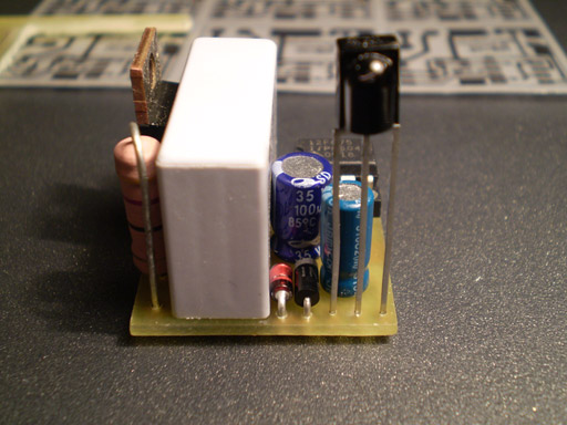
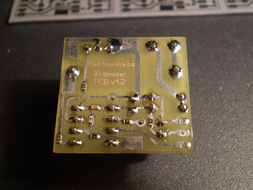
This is a very simple IR light dimmer that you will wish to have sooner or later, especially those who are lazy enough to get up and turn off the lights. There are two versions of PCB for two sizes of capacitors, so PCBs are: 32.5 x 26.5mm and 28.5 x 27mm.
You can download the project files at the bottom of this page by clicking on red "download" button.

Features of current beta version of firmware:
- Soft start (gradually turning on the light bulb)
- Soft down (gradually turning off the light bulb)
- Learning IR codes from RC5 and NEC remotes
- Dimming in 10 levels by using only IR remote
- Previous dimm-level remembering when operating with remote
- Sleep timer in duration of 1.6min for 60Hz version and 2min for 50Hz version
- ON/OFF control with wall pushbutton
Dimmer is connected to existing home wiring installation inside a junction box, which is usually located above the light switch. In order to properly connect the dimmer to installation one should follow the schematics provided for that purpose. If connected differently there is a very big chance of some freaky side effects such as burned PIC microcontroller, serious fire and who knows what else.
Learning remote control IR codes (programming procedure)
After connecting dimmer to installation you must program the remote control buttons. Here is how to do that:
1. Hold the wall pushbutton for 11 sec so that dimmer can enter programming mode. After those 11 sec, LED will start to blink fast, and light will dimm to third (3.) level. Now you have 11 sec to complete the programming sequence:
2. Press the first button on your remote that will increase light level or turn on the light when it is turned off (ON/UP)
3. Press the second button on your remote that will be used to decrease the light level (DOWN)
4. Press the third button that will be used for activating/deactivating sleep mode (SLEEP)
5. Finally, press the fourth button that will be used to turn off light completely (OFF)
During programming, both the light bulb and LED will blink to confirm IR code reception. If your remote control does not have all 4 buttons that you can use, you can repeat previous button but that will cancel out some features. For example, if your remote has only two buttons (A and B), and if during programming you press: A A A B, that means that key A will be used for ON/UP function, and key B will be used to completely turn off the light. If you choose combination A B B B, it means that the key A will be again used for ON/UP function, and key B will be used to decrease light level (it will also turn the light off completely in 10 button presses - until zero level).
Programming notice: If during programming, you notice that LED blinks even when you don't press any buttons on your remote control, it is probably because you used TSOP11xx instead of TSOP17xx receiver module. In that case, you will probably not be able to program your dimmer properly.
If you are not satisfied with your choice of remote controller buttons, you can repeat the learning procedure as much as you like.
If you are planning to use your TV's remote controller, you should probably choose those teletext buttons: red, green, yellow and blue to avoid, for example, switching channels when operating the dimmer.
Sleep timer
Sleep timer can be activated by a bit longer wall-pushbutton press, more than 1.8 sec to be precise, or by pressing the appropriate button on the remote controller. Sleep timer cancellation is accomplished just like the activation. It is possible to increase/decrease the light level when sleep timer is active. Dimmer will automatically set the light level to six (6) when entering the sleep mode, but only if previous level was greater than 6.

Important notice: This device is connected to mains power line, so it requires a lot of respect. If you are not sure in what you are doing, you better leave the installation part to the experienced electrician.
Dimmer in operation:
Note: Dimmer works better with TIC206 rather than TIC216!
Author (sent by): Trax
Download counter: 55,395
Rating: 

 (3.00, votes 8291)
Date: 07-02-2009
Lokalna verzija ove stranice: IR dimmer svjetla v1
You can download schematics by clicking on the RED DOWNLOAD button just above these comments...
IP: n/a
Can you just post a scheme up again?? or you can send it to me in PM!!
Thank you.
IP: n/a
There is a transformerless power supply device in the circuit and it regulates 220V to 5V. If
you are not experienced with high voltages, please do not build this circuit as it is not safe
for beginners. Even with this 5V power supply, you CAN NOT touch anything while it is powered.
IP: n/a
I have a small question now I Know that pic work with 5V for vdd so I see that u connect it
directly to AC volt so how it works ?
IP: 41.238.111.190
oops..it didnt show any chars in between. it should be. pic pin 7---470R---moc3023 pin 1. moc
pin 2---ground. moc pin 4--triac 3(gate). moc pin 6---390R---triac pin2.
IP: n/a
to toose: im trying to understand comments using translator and its not accurate. are you
asking how moc3023 was connected? if so, i took out r2. then connected
pic pin 7470Rmoc3023 pin 1.
moc pin 2ground.
moc pin 4triac 3(gate).
moc pin 6390Rtriac pin2.
and as Master Trax said, we can now use any triac with moc3023.
to Master Trax: every pin is so busy and happy except for the sad and lonely pin4. please make
pin4 happy by making it play with the others...Happy New Year to All.God bless!!
IP: n/a
kako da povrzam MOC3023 ima li nekoj idea i sema?
IP: 89.205.95.182
Hello again Master Trax. i need to light an LED when lamp is off. i am thinking of tapping the
signal coming out of pin 7 then input it to another pic interrupt pin to monitor if the light
is on or off then light an LED when its off. But i noticed that in your circuit pin 4 can do
this function. I know that your a busy person and have already given so much to many people. I
am just going to try my luck (cross fingers) in asking if you will give us hex file for this.
More power to you Master Trax!
IP: n/a
Its done!!!Im so happy!!Worked like magic. How much current can i still draw from the circuit?
I was thinking of adding few RGB LEDs. Thank you so much Master Trax!!!!!!!!!
IP: n/a
You can log-in on forum link: Login page. After logging-in, return to this page and click refresh in your browser.